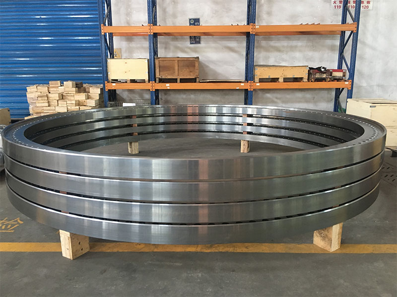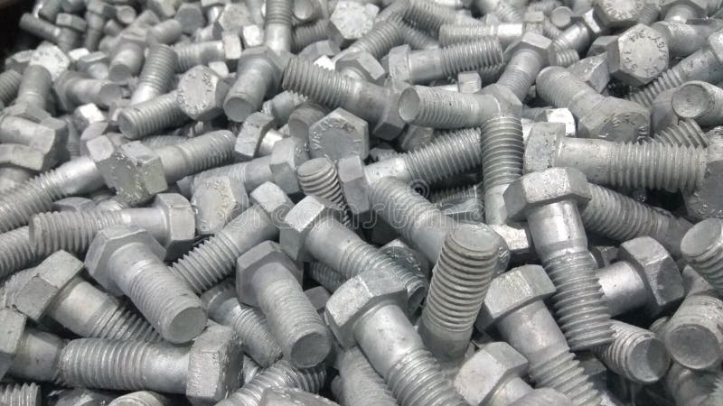
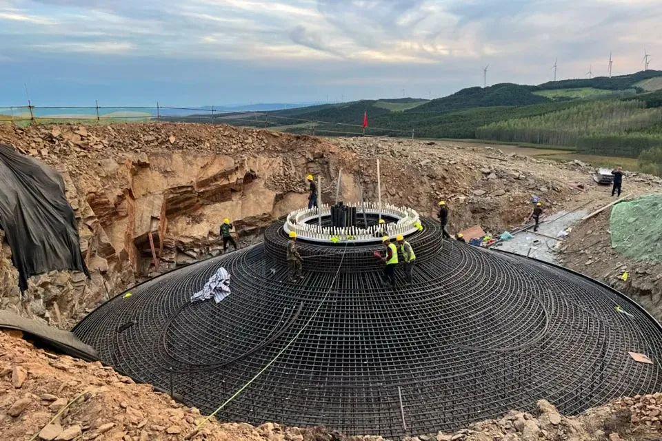
A modern wind turbine foundation is a highly engineered structural system. Beneath the tower base flange sits a circular concrete foundation designed to resist overturning moments, fatigue loads and millions of load cycles throughout a 20–25 year service life. The connection between the steel tower and the concrete foundation depends on one critical component: the foundation anchor bolt system.
Unlike ordinary structural bolts that remain accessible for inspection and replacement, foundation anchors are embedded into concrete and grout after installation. Their material grade, corrosion protection, thread quality, preload level and installation procedure must therefore be correct before commissioning. A mistake in anchor selection can lead to preload loss, flange movement, grout cracking, corrosion concerns and costly corrective work at an operating wind farm.
WF Fastener manufactures wind turbine foundation anchor bolts, anchor cage systems and custom foundation fasteners for EPC contractors, turbine foundation suppliers and renewable energy projects across Europe, the Middle East and Southeast Asia. Our production follows ISO, EN and DIN standards, with project-specific requirements mapped to customer drawings and turbine OEM specifications.
This engineering guide covers:
- Modern prestressed anchor cage systems
- L-type and J-type foundation anchors
- S355 and 42CrMo4 property class 10.9 materials
- Hot-dip galvanizing according to ISO 10684
- Grout requirements under turbine base flanges
- Hydraulic tensioning and preload control
- Inspection documentation for wind farm acceptance
For the complete renewable-energy fastener range, see our renewable energy fastener manufacturer center.
Why Foundation Anchoring Is the Most Critical Bolted Joint on a Wind Farm
Foundation anchor bolts are not simply oversized bolts. They form a complete load-transfer system between the turbine tower and reinforced concrete foundation.
Three engineering factors make this connection different from conventional bolting:
1. The anchor system becomes inaccessible after installation
Once the concrete foundation and grout are completed, most of the anchor length is permanently embedded. Unlike tower flange bolts, which can be accessed with hydraulic tensioners during maintenance, foundation anchors cannot easily be replaced.
This means the following must be controlled before concrete pouring:
- Rod material and mechanical properties
- Thread accuracy
- Galvanizing quality
- Nut compatibility
- Embedment length
- Preload procedure
The quality requirement is therefore front-loaded. Correct installation is much more important than later maintenance.
2. The load path transfers into concrete
A foundation anchor does not only resist bolt tension. It transfers loads through the interaction between:
- Steel rod strength
- Lower anchor plate or nut geometry
- Concrete compressive strength
- Embedment depth
- Anchor spacing
- Concrete breakout resistance
The foundation engineer designs the complete system according to concrete fastening requirements, typically including EN 1992-4 principles for fastenings in concrete.
3. The loading is cyclic for decades
A turbine foundation experiences:
- Wind-induced bending moments
- Rotor imbalance loads
- Start-stop cycles
- Emergency braking events
- Turbulence and fatigue loading
The anchor cage maintains compression between the tower flange and grout layer so that cyclic tension does not repeatedly open the joint.
For this reason, modern turbine foundations use preloaded anchor systems, not simply tightened bolts.
Foundation Anchor Bolt Types: L-Type, J-Type and Prestressed Anchor Cages
L-Type and J-Type Cast-In Anchor Bolts
L-type and J-type anchors are traditional foundation fasteners used mainly on smaller turbines, auxiliary structures and older turbine designs.
The rod is bent at one end:
- L-type: approximately 90-degree bent leg
- J-type: hooked end providing mechanical engagement
The bent section transfers tensile forces into the surrounding concrete.
Typical characteristics:
| Item | Typical specification |
|---|---|
| Material | S355JR / S355NL structural steel |
| Size range | M30–M48 |
| Installation | Cast directly into concrete |
| Corrosion protection | Hot-dip galvanized |
| Application | Smaller turbines, older designs, simple foundations |
Advantages:
- Simple installation
- Lower material cost
- Familiar to civil contractors
Limitations:
- Limited preload capability
- Greater sensitivity to concrete relaxation
- Less suitable for large modern turbines with high cyclic loads
For utility-scale turbines above several megawatts, L/J anchors have largely been replaced by prestressed anchor cages.
Prestressed Anchor Cage Systems for Modern Wind Turbines
Most modern multi-megawatt onshore and nearshore turbines use a prestressed anchor cage system.
The cage consists of multiple high-strength threaded rods arranged in a circular pattern around the tower foundation.
Typical rod sizes include:
- M42
- M48
- M56
- M64
The system normally includes:
- Double-ended threaded rods
- Lower anchor nuts or bearing plates
- Upper adjustment nuts
- Washers
- Thread protection components
- Installation accessories
How the Anchor Cage Works
The foundation sequence is typically:
- Anchor cage positioned inside reinforcement steel.
- Concrete foundation poured around the embedded system.
- Tower base flange installed on upper nuts.
- Hydraulic tensioning applies preload to each rod.
- Non-shrink grout fills the gap below the flange.
- Final tensioning completes the load transfer.
The objective is not simply to tighten the bolts. The objective is to maintain a permanent compression zone between:
- Tower flange
- Grout layer
- Concrete foundation
This prevents cyclic separation under turbine operating loads.
Why Double-Ended Threaded Rods Are Used
Double-ended rods provide several advantages:
- Upper thread allows hydraulic tensioning
- Lower thread connects to anchoring components
- Rod length can be optimized for foundation geometry
- Preload can be adjusted after installation
The anchor cage should always be treated as a matched assembly.
Mixing:
- Rods from one supplier
- Nuts from another supplier
- Different galvanizing systems
can create problems with:
- Thread engagement
- Friction coefficient
- Galvanizing thickness
- Nut compatibility
For large wind projects, the complete rod, nut and washer package should be supplied together.
Materials: S355 vs 42CrMo4 Property Class 10.9
Material selection depends on turbine size, foundation design and required preload level.
| Position | Material / Grade | Property Class | Typical Application |
|---|---|---|---|
| L/J anchor bolts | S355JR / S355NL (EN 10025) | Structural grade | Smaller turbines and traditional foundations |
| Anchor cage rods | 42CrMo4 (EN 10083-3), quenched and tempered | 10.9 per ISO 898-1 | Modern multi-MW turbines |
| High-load anchor systems | 42CrMo4 or equivalent alloy steel | 12.9 where specified | Large rotor and high-load foundations |
| Anchor nuts | Matched alloy steel | Class 10 / 12 ISO 898-2 | Must match rod strength |
Why 42CrMo4 Is Used for Modern Anchor Cages
42CrMo4 is a chromium-molybdenum alloy steel commonly used for high-strength applications.
After quenching and tempering, it achieves the mechanical properties required for class 10.9 fasteners.
Typical ISO 898-1 class 10.9 minimum values:
- Tensile strength (Rm): ≥ 1040 MPa
- Yield strength (Rp0.2): ≥ 940 MPa (depending on diameter)
- High fatigue resistance compared with structural steels
The important specification point is:
The alloy name alone is not enough. The required property class and heat-treatment condition must be specified.
A drawing should state:
42CrMo4 quenched and tempered, property class 10.9 according to ISO 898-1
rather than only:
42CrMo4 material
Nut Matching Requirements
Foundation anchor nuts must match the rod strength level.
Typical combinations:
- 10.9 rod → Class 10 nut
- 12.9 rod → Class 12 nut
An under-strength nut can become the failure point even when the rod is correctly specified.
Hydrogen Embrittlement Considerations
High-strength fasteners are more sensitive to hydrogen-assisted cracking than ordinary structural steel.
For 10.9 and above anchor rods:
- Galvanizing process must be controlled
- Acid pickling time must be controlled
- Hydrogen relief baking requirements must be followed where applicable
- Final hardness must remain within specification
This is why foundation anchor galvanizing requires more process control than normal galvanized steel products.
Global EPC Project Specification Equivalents
Depending on project origin and owner standards, customers may specify the following widely recognized international standards as alternatives alongside the ISO/EN manufacturing system:
| Topic | International standard | Relationship to ISO/EN practice |
|---|---|---|
| Anchor bolt material and strength | ASTM F1554 | Specification for anchor bolts intended for concrete attachment; grades 36, 55 and 105 correspond to common yield/tensile levels |
| Concrete anchor design | ACI 318 Chapter 17 | Structural concrete provisions for anchor design, including breakout, pull-out and side-face blowout |
| Structural steel connection design | AISC 360 | Specification for structural steel buildings; referenced for tower base flange and connection design checks |
These standards are provided as customer-specified equivalents. The primary manufacturing and material requirements on approved turbine foundation drawings continue to follow ISO, EN and turbine OEM specifications unless the project explicitly calls up ASTM F1554, ACI 318 or AISC 360.
Hot-Dip Galvanizing: ISO 10684 Requirements
Foundation anchors experience two different environments:
- Embedded section inside concrete and grout
- Exposed upper threads and nuts above the foundation
Both require corrosion protection.
For fasteners, the relevant standard is:
ISO 10684 — Hot dip galvanized coatings on threaded fasteners
This standard defines:
- Zinc coating thickness
- Thread allowance
- Nut tapping requirements
- Compatibility between bolt and nut
Key Requirements for Wind Foundation Anchors
Coating Thickness
Large anchor rods such as M42–M64 typically require heavy zinc coating.
For large diameter fasteners, coating thickness is commonly around:
- 85 µm minimum range depending on specification
- Measured and recorded during inspection
A supplier certificate should show actual coating measurements, not only "HDG supplied."
Galvanized Nut Compatibility
Galvanized nuts are not simply standard nuts dipped in zinc.
Because the zinc layer increases thread dimensions:
- Nuts are tapped oversize
- Bolt and nut thread engagement must be checked together
Supplying rods and nuts as a matched galvanized set avoids installation problems.
Field Cutting Is Not Recommended
Foundation anchor rods should be supplied at the final required length.
Avoid:
- Cutting galvanized rods on site
- Re-threading after galvanizing
- Damaging exposed threads
A damaged galvanized thread becomes a corrosion initiation point that is difficult to repair after installation.
Coastal Wind Farms
Nearshore and offshore-adjacent projects may face:
- Salt spray
- High humidity
- Chloride contamination
For aggressive environments such as ISO 12944 C5-M exposure, additional systems may be specified:
- Duplex coating systems
- Zinc-flake coatings
- Protective topcoats
For more information on corrosion protection systems, see our hot-dip galvanized and Zn-Al-Mg renewable fasteners guide.
Grout Design Under the Tower Base Flange
After the tower base flange is positioned and leveled on the upper anchor nuts, the gap between the steel flange and concrete foundation is filled with non-shrink (shrinkage-compensated) grout.
The grout layer is not simply a filler. It is a structural component of the load-transfer system.
The grout performs three primary functions:
1. Uniform load transfer
The tower flange should not bear directly on uneven concrete.
The grout layer:
- Creates a continuous bearing surface
- Distributes compression across the flange area
- Prevents local stress concentrations
- Maintains tower alignment
A poor grout installation can create uneven contact pressure and increase fatigue loading on the anchor system.
2. Protection of the foundation interface
The grout helps protect:
- Lower exposed threads
- Anchor nuts
- Foundation interface areas
against moisture ingress and contamination.
3. Maintaining tower geometry
During installation, anchor nuts are used to level the tower flange.
After grout curing, the grout locks the final position and provides a stable bearing surface.
Typical Grout Requirements
Wind turbine foundation specifications commonly require:
| Property | Typical Requirement |
|---|---|
| Type | Non-shrink cementitious grout |
| Compressive strength | 50–80 MPa at 28 days |
| Early strength | Often specified for installation schedule |
| Shrinkage | Expansion compensated / controlled shrinkage |
| Placement | Pumped, self-leveling, void-free installation |
| Thickness | Typically 30–50 mm depending on OEM design |
The exact grout specification remains turbine OEM and foundation-design dependent.
Important coordination points between the anchor supplier and civil contractor include:
- Anchor rod protrusion height
- Upper nut engagement
- Washer thickness
- Required grout gap
- Final flange elevation
The fastener supplier does not normally provide the grout material, but the anchor dimensions must be compatible with the grout design.
Concrete Design: Anchor Embedment and Failure Modes
The steel rod is only one part of the foundation anchoring system. The concrete around the anchor must resist the transferred loads.
Foundation designers typically evaluate anchor behavior according to:
- EN 1992-4 — Design of fastenings for use in concrete
- Applicable turbine OEM foundation standards
- Project-specific structural requirements
Important concrete failure modes include:
Concrete Cone Breakout
Under excessive tension, a cone-shaped section of concrete can separate around the anchor.
Resistance depends on:
- Effective embedment depth
- Concrete strength
- Anchor spacing
- Edge distance
- Anchor arrangement
Pull-Through Failure
The lower anchor plate or nut transfers force into the concrete.
The design must prevent:
- Plate punching
- Local concrete crushing
- Pull-through of embedded components
Concrete Splitting
Closely spaced anchors or insufficient reinforcement can create splitting forces.
The foundation design controls:
- Anchor spacing
- Reinforcement arrangement
- Concrete cover
- Edge distances
Long-Term Preload Loss
Concrete experiences:
- Shrinkage
- Creep
- Relaxation
over the turbine service life.
The initial preload must therefore account for long-term losses.
For procurement teams, the key point is:
The anchor bolt supplier must manufacture exactly to the approved foundation drawing.
Critical dimensions include:
- Number of rods
- Bolt circle diameter
- Rod length
- Thread length
- Embedment arrangement
- Upper projection height
Torque and Preload Procedure for Foundation Anchor Bolts
Foundation anchors are prestressed structural elements, not ordinary tightened bolts.
The installation objective is to create a controlled tensile force in each rod while maintaining compression between the tower flange and foundation.
Typical Installation Sequence
Step 1: Position and Level the Tower Flange
The tower section is positioned on the upper anchor nuts.
The flange elevation and level tolerance are adjusted before final tensioning.
Step 2: Hydraulic Tensioning
Modern wind turbine foundations typically use hydraulic bolt tensioners.
The normal sequence includes:
- Initial tensioning pass
- Opposite-side or diagonal sequence
- Multiple circumferential passes
- Final verification pass
The purpose is to reduce load scatter between individual rods.
Step 3: Grouting
After initial tensioning:
- Non-shrink grout is installed
- Grout cures according to OEM requirements
- Final structural bearing condition is established
Step 4: Final Tensioning
After grout curing:
- Final preload is applied
- Lock nuts are installed if specified
- Witness marks may be applied for inspection
Typical Preload Values
For class 10.9 anchor rods, many turbine systems target approximately:
70–80% of yield strength
However, the actual value depends on:
- Turbine model
- Foundation design
- Rod diameter
- OEM installation procedure
- Allowance for relaxation
Example approximate values:
| Rod Size | Tensile Stress Area | Typical Preload Range |
|---|---|---|
| M48 10.9 | ~1470 mm² | ~900–1050 kN |
| M56 10.9 | ~2030 mm² | ~1.2–1.5 MN |
These values are examples only. Final preload must always follow the approved turbine foundation procedure.
Torque vs Hydraulic Tensioning
Torque is affected by:
- Thread friction
- Zinc coating condition
- Lubricant type
- Nut factor variation
Therefore:
- Large anchor cages → hydraulic tensioning preferred
- Smaller foundation anchors → torque methods may be acceptable
A generic torque table should never replace the turbine OEM procedure.
Never:
- Mix tensioning methods randomly
- Tighten by "snug plus turn"
- Apply uncontrolled impact tools
Quality Control and Inspection Documentation
For utility-scale wind projects, foundation anchor bolts require a complete traceability package.
A typical inspection package includes:
Material Certificates
EN 10204 3.1 certificates should include:
- Heat number
- Chemical composition
- Mechanical properties
- Heat-treatment condition
For major utility projects, EN 10204 3.2 third-party inspection may be specified.
Non-Destructive Testing
Depending on project requirements:
- Ultrasonic testing
- Magnetic particle inspection
- Surface inspection of threaded areas
are used to identify potential defects.
Galvanizing Inspection
Documentation should include:
- ISO 10684 compliance
- Coating thickness measurements
- Visual inspection results
Thread Inspection
Critical checks:
- Thread dimensions
- GO/NO-GO gauge results
- Nut compatibility
- Thread coating condition
Traceability
Every rod and nut should be traceable to:
- Material heat
- Production batch
- Inspection record
- Packing list
For multi-wind-farm EPC programs, certificate organization by foundation ring can significantly simplify site acceptance.
Quick-Reference Specification Table
| Item | Typical Specification |
|---|---|
| Anchor system | Prestressed anchor cage for modern turbines |
| Anchor rod sizes | M42, M48, M56, M64 |
| Traditional anchors | L/J type M30–M48 |
| Cage rod material | 42CrMo4 Q+T |
| Mechanical class | 10.9 per ISO 898-1 |
| High-load option | 12.9 where specified |
| Nut specification | Class 10/12 ISO 898-2 |
| Corrosion protection | HDG ISO 10684 |
| Coastal protection | Duplex coating / zinc-flake / topcoat where required |
| Grout type | Non-shrink cementitious grout |
| Typical grout strength | 50–80 MPa at 28 days |
| Installation method | Hydraulic tensioning |
| Typical preload | Approximately 70–80% Rp0.2 according to OEM procedure |
| Concrete design | EN 1992-4 principles; ACI 318 Ch.17 and ASTM F1554 as customer-specified US equivalents |
| Documentation | EN 10204 3.1, 3.2 if required, UT, galvanizing records |
Related Guides
This article is part of our renewable-energy fastener engineering series:
- Renewable energy fastener center — solar, wind, grid
- Wind tower flange bolts to EN 14399
- BESS rack and battery cabinet fasteners
- Custom drawing fasteners made to your foundation detail
FAQ
Which anchor bolt system is used for modern wind turbines?
Modern multi-megawatt turbines typically use prestressed anchor cage systems with double-ended threaded rods, commonly M42–M56, manufactured from quenched and tempered alloy steel such as 42CrMo4 to property class 10.9. L-type and J-type anchors are mainly used on smaller turbines or older foundation designs.
What material are wind turbine foundation anchor bolts made from?
Modern anchor cage rods are commonly made from 42CrMo4 alloy steel, quenched and tempered to property class 10.9 according to ISO 898-1.
Traditional cast-in anchors may use structural steels such as S355JR or S355NL.
The specification should always define:
- Material grade
- Heat treatment
- Property class
- Mechanical requirements
Are wind turbine foundation bolts hot-dip galvanized?
Yes. Foundation anchor systems commonly use hot-dip galvanizing according to ISO 10684.
Important controls include:
- Coating thickness measurement
- Galvanized nut compatibility
- Thread inspection
- Prevention of damaged threads after coating
For aggressive coastal environments, additional coating systems may be specified.
How are wind turbine foundation anchor bolts tightened?
Large foundation anchor systems are normally tensioned hydraulically rather than tightened only by torque.
The installation procedure usually includes:
- Initial tensioning
- Multiple tensioning passes
- Grouting
- Final tensioning after grout curing
The target preload is determined by the turbine OEM and foundation design.
What grout is used under a wind turbine base flange?
Wind turbine foundations normally use non-shrink cementitious grout with controlled expansion characteristics.
Typical requirements include:
- 50–80 MPa compressive strength at 28 days
- Pumpable installation
- Void-free placement
- Compatibility with OEM foundation requirements
What certificates are required for foundation anchor bolts?
Typical documentation includes:
- EN 10204 3.1 material certificates
- Third-party 3.2 inspection when specified
- Mechanical test reports
- Galvanizing certificates
- Thread inspection records
- Traceability records
Large wind projects often require full documentation before foundation acceptance.
Can you manufacture custom wind foundation anchor cages?
Yes. WF Fastener supplies custom foundation anchor systems based on approved drawings.
Capabilities include:
- Custom rod lengths
- Special thread dimensions
- Matched nuts and washers
- Custom galvanizing requirements
- Project-specific documentation packages
Send the foundation drawing or anchor schedule, and our engineering team can review the material, dimensions and inspection requirements.
Talk to Our Engineering Team
Whether you are an EPC contractor preparing a wind farm tender, a foundation supplier requiring matched anchor cage hardware, or an OEM replacing existing turbine foundation components, WF Fastener can support the complete specification review.
We can confirm:
- Anchor rod material and property class
- Galvanizing requirements
- Thread and nut compatibility
- Preload requirements
- Inspection documentation
Send your foundation drawing, anchor bolt schedule or turbine model information before issuing the purchase order.
- Email our engineering team: engineering@wffastener.com
- WhatsApp: [+86 XXX XXXX XXXX] — share the turbine model, foundation drawing and site corrosion category (C3/C4/C5-M), and we will provide a matched anchor solution with documentation and lead time.